|
J.Orthopaedics 2007;4(1)e2
Objectives:
A plethora of Spinal Screw
Rod systems are available as of today. However most if not all
have issues as regards closure mechanism and biomechanics.
Though these issues may seem to be of trivial importance during
surgery, the long-term effects of such implantations may be
catastrophic[13]. Other than addressing these issues, the One
Lock Screw Rod System, by virtue of its indigenity, also
addresses the issue of high cost. The design objectives of the
One Lock screw rod system are high closure security, a low
fiddle factor and a high resistance to bending loads.
Material and Methods :
The entire study was
conducted in the Department of Mechanical Engineering at the
Indian Institute of Technology, Powai Mumbai .The central
research committee of the Indian Institute of technology
approved the study.
The study and testing of the
system was carried out as per the standard ASTM F:1798
1997, Standard Guide for evaluating the static and fatigue
properties of interconnection mechanisms and sub-assemblies used
in spinal arthrodesis implants.
The study was performed using
a Universal testing machine (UTM) . The automated 50 kN UTM,
[Lloyds U.K - Model no EZ 50] was connected to a Windows based
software, [National Instruments, U.K] providing continuous load
displacement graphs. Four variants of the One Lock were tested
initially. Since the MUV variant was found to be the most
superior amongst all the variants, the final tests were
performed on this variant only.
For the purpose of accuracy,
the Zero error which is minimal in the automated UTM was
calculated for the particular machine and was entered into the
computer programme .This would nullify all the false negative
values. A metallic fixture was designed to hold the MUV variant.
This in-turn perfectly reciprocated with the mechanical levers
of the UTM. The design of the fixture assured a snug fit,
minimizing the toggle effect between the implant and the
fixture. In order to rule out technical errors, each of the
tests was repeated six times and only the average readings were
reported.
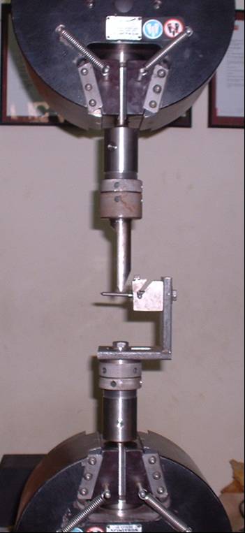
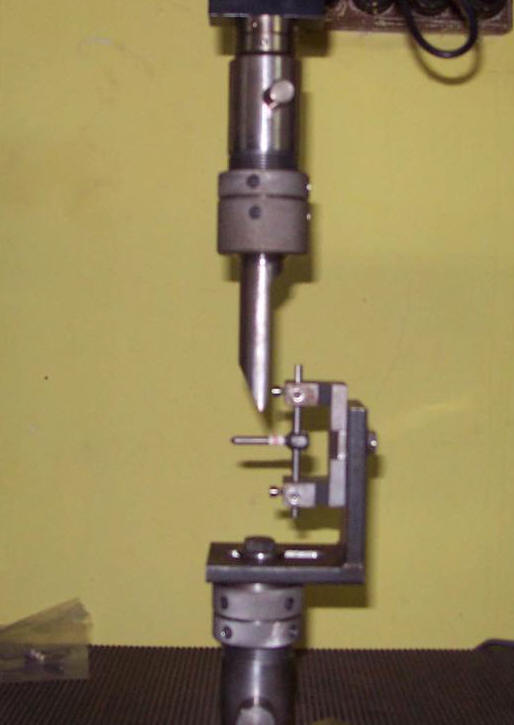
Axial Loading Test ( Picture
1,2,3)
Assembly of the screw rod
unit was performed before mounting . A Universal Torque screw
driver was used for tightening the nut ensuring uniform
tightening of the inner set screw to the recommended value.
After vertical mounting, a
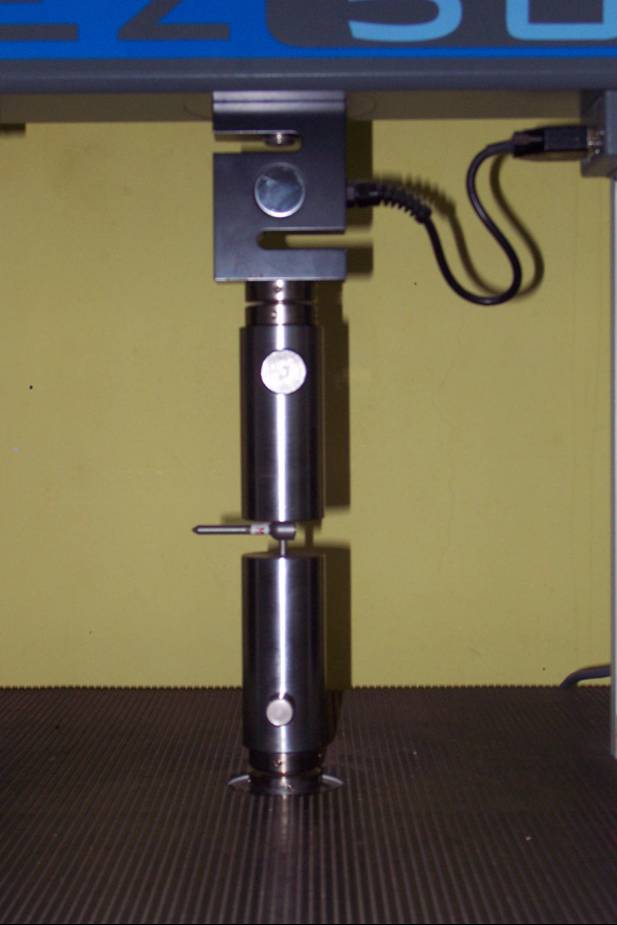 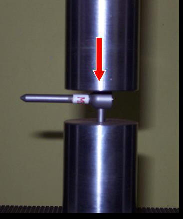  graduated
force was applied to the assembly in the direction parallel to
the rod with the force nucleus being the centre of curvature of
the rod. The force tried to simulate and exceeded the actual
environment of the axial forces which are transmitted to the
screw rod interface. The Force at which there was a uncoupling
of the screw rod assembly was assessed and was digitally
plotted ( Figure 1). graduated
force was applied to the assembly in the direction parallel to
the rod with the force nucleus being the centre of curvature of
the rod. The force tried to simulate and exceeded the actual
environment of the axial forces which are transmitted to the
screw rod interface. The Force at which there was a uncoupling
of the screw rod assembly was assessed and was digitally
plotted ( Figure 1).
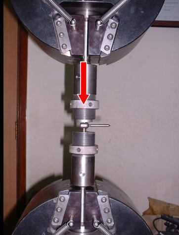
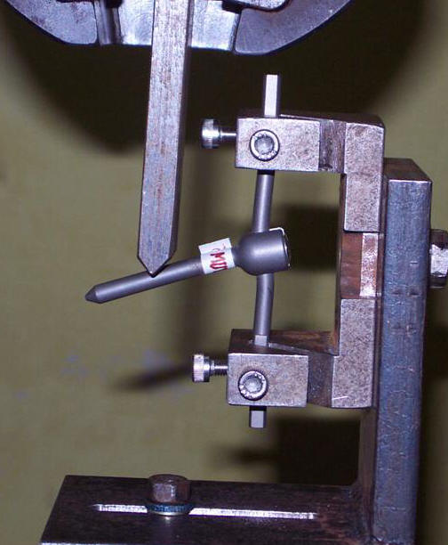
Torsional loading Test (
Picture 4,5)
Similar to Axial loading
test, a screw rod assembly was coupled. The assembly was mounted
horizontally within the fixture and a graduated force was
applied
  at a point as defined in the test method. The loading
points were accurately measured and pre-marked with a metallic
marker. This was done in order to simulate the point at which
the actual forces precipitate when such a construct is used as a
posterior spinal instrumentation in the human spine. The
Force at which there was a uncoupling of the screw rod
assembly in torsion, was assessed and was digitally plotted
similar to the previous described test (Figure 2) at a point as defined in the test method. The loading
points were accurately measured and pre-marked with a metallic
marker. This was done in order to simulate the point at which
the actual forces precipitate when such a construct is used as a
posterior spinal instrumentation in the human spine. The
Force at which there was a uncoupling of the screw rod
assembly in torsion, was assessed and was digitally plotted
similar to the previous described test (Figure 2)
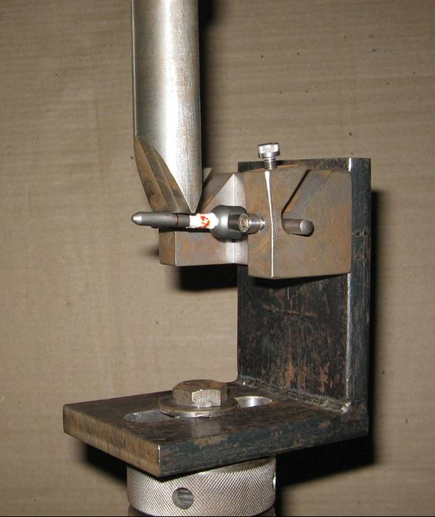
Bending Moment Test ( Picture
6,7)
An screw-rod construct
assembly, similar to the construct used as a posterior spinal
instrumentation in the human spine was created. This construct
was
  mounted vertically on a specially designed fixture which
simulated the conditions of Flexion and extension as would occur
on the human spine in vivo. A controlled force was applied in a
graduated manner at a pre-marked point on the screw as defined
by the test method. The force at which there was a mechanical
failure of the construct leading to deformation of the construct
was assessed and the graph was plotted. mounted vertically on a specially designed fixture which
simulated the conditions of Flexion and extension as would occur
on the human spine in vivo. A controlled force was applied in a
graduated manner at a pre-marked point on the screw as defined
by the test method. The force at which there was a mechanical
failure of the construct leading to deformation of the construct
was assessed and the graph was plotted.
Head Spread ( Picture 8,9)
To study Splaying of the head
after torque tightening of the screw, the screw
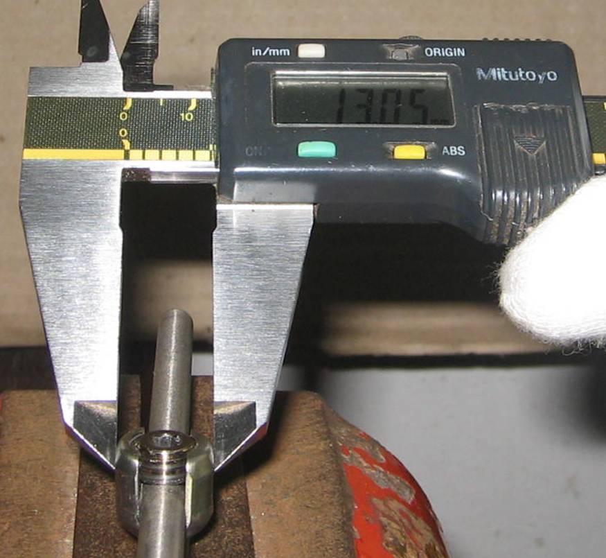
 rod assembly
was coupled and the Nut was tightened with a torque screw driver upto the recommended tightening torque as is routinely done in
the last step of final tightening. The splaying of the head was
measured with the help of Digital calipers as shown in the
picture. rod assembly
was coupled and the Nut was tightened with a torque screw driver upto the recommended tightening torque as is routinely done in
the last step of final tightening. The splaying of the head was
measured with the help of Digital calipers as shown in the
picture.
Results :
Axial Load Testing
The
OneLock spine screw-rod construct was found to have an axial
slip load of 3222 Newtons.
Fig
1 Depicts the Load at which axial slip occurs at the screw
rod interface
 Torsional Loading Test
The
Torsional Slip Load of the OneLock screw-rod construct was
found to be 9.61 Nm.
Torsional Loading Test
The
Torsional Slip Load of the OneLock screw-rod construct was
found to be 9.61 Nm.
Figure 2 Depicts the Load at which Torsional slip occurs
at the screw rod interface
Flexion
Extension Moment Test
The
flexion extension moment of the OneLock screw-rod construct was
found to be 23.5 Nm
Figure 3 depicts the flexion extension moment
Head
Spread
The
Head Spread of the MUV variant was 0.05 mm at recommended
Tightening Torque.
Discussion :
Pedicle
screws have been used for instrumentation of the spine since
the mid eighties. With the passage of time and refinements in
the field of Biomedical engineering, understanding of the
biomechanics of pedicular screw rod systems have significantly
improved [1,3,4,6,7,8].
A
review of the currently available systems revealed certain
issues regarding implant biomechanics and closure mechanism at
the screw rod interface.
The
conventional Double Locking Screw Rod interface systems have a
three step closure. Approximation of the rod to the screw by
applying the inner nut, reinforcement of the locking by an
outer nut and in the final step, re-tightening of the inner
nut with a Torque Screw Driver. The primary issues faced by
surgeons with these systems were Cross threading of the inner
nut and a hindrance to loading of the outer nut when the inner
nut was fully tightened. These issues made the the use of
Double locking systems time consuming and cumbersome
especially during surgeries for spinal deformity corrections.
The
earlier available versions of the single locking screw-rod
interface systems had bulky screw heads which lead to
prominence when used in children and lean individuals. These
earlier locking mechanism designs of the inner nut did not
provide adequate gripping force thus leading to occasional
interface failure[2,4,8.10.11.12]. Additionally head splaying
was evident during the final torque tightening which further
exacerbated the problems. Though the subsequent improved
versions promised to address these issues, the issue of head
splaying, observable in various well known systems, still
remained pertinent. The reason for persistence was that, on
tightening the locking screw, the dissipation of the
horizontal vector of force applied leads to splaying of the
head.
Some
versions of reduction screws used in Spondylolysthesis have a
bulky head. They also have an indirect locking mechanism and
need approximation of the tabs which is an additional
procedural step.
The
variable designs of the tapered screws have issues of removal,
since once the screw head is locked, it cannot be unlocked.
Additionally head splaying is evident when he inner nuts are
tightened. Screws with multiple components require to be
assembled on the table and are not preferred for load-bearing
applications such as a lumbar spine construct[14,15,16]. The
lateral offset type of polyaxial screws have a fiddly locking
mechanism which be cumbersome during usage.
In
summary most systems have Closure Mechanismissues. Systems
with low fiddle factor have a low connection security and
those with a high fiddle factor offer a high connection
security.
The
OneLock system was designed to address these issues. The
Torsional slip of the One Lock System was 9.61 Nm which is
better than most of the currently available systems. The
flexion Extension moment, a critical indicator of performance
in a real life load bearing construct, at 23.5Nm is also
superior to most of the available systems.
As
regards head splaying, the OneLock strives to achieve the
Paradigm shift, that is to prevent splaying in the first
instance.The mechanism by which this is achieved is the square
threaded design of the inner set screw combined with the
proprietary design of the screw head profile. With the square
threads, tightening the inner screw transmits 100 % of the
torque axially to the rod without dissipation. The proprietary
design of the screw head profile absorbs residual outward
forces. Hence unlike an standard thread of many known systems,
there is no resultant dissipation of the tightening torque.
This leads to minimization of head splaying. Compared to the
best contemporary designs (0.11 mm), there is a 50% reduction
(0.5 mm ) in the head splay at recommended tightening torque.
Conclusion:
The
OneLock pedicle screw rod system is a easy to use Single step
closure system with a best in the class head spread, a torsional
grip strength higher than most known systems, a bending moment
resistance higher than most known systems, an axial grip
strength higher than most known systems at comparable and
competitive cost levels.
Reference
-
Abumi k.,
Panjabi,MM, Duranceau J., (1989). Biomechanical evaluation of
spinal fixation devices. Part III. Stability provided by six
spinal fixation devices and interbody bone graft. Spine 14,
1249-1255
-
An.HS.,
Singh K., Vaccaro, AR., Wang G., Yoshida, H., Eck J., McGrady,
L., Lim, TH , (2004). Biomechanical evaluation of contemporary
posterior spinal internal fixation configurations in an unstable
burst-fracture calf spine model: special references of hook
configurations and pedicle screws.Spine 29,257-262
-
Goel,VK,
Lim TH., Gwon,J., Chen, JY., Winterbottom, JM.,Park,JB.,
Weinstein,JN, Ahn., JY (1991). Effects of rigidity of an
internal fixation device. A comprehensive biomechanical
investigation.Spine 16 ( Suppl 3) 155-161
-
Gurr KR,
McAfee PC, Warden KE, Shih CM ( 1989) Roentgenographic and
biomechanical analysis of lumbar fusions: a canine model .J
Orthop Res 7:838.
-
Horowitch
A,Peek RD,Thomas JC Jr,Widell EH Jr, DiMartino PP, Spencer CW 3rd,
Weinstein J, Wiltse LL (1989) The Wiltse pedicle screw fixation
system. Early clinical results. Spine 14:461-467
-
Krag MH
.(1991). Biomechanics of thoraciclumbar spinal fixation.A
review.Spine 16:S84-99.
-
Leong JC,
Chun SY, Grange WJ, Fang D. (1983). Long-term results of lumbar
intervertebral disc prolapse.Spine 8: 793-799
-
Marchesi
DG, Aebi M. (1992). Pedicle fixation devices in the treatment of
adult lumbar scoliosis. Spine 17:S304-309
-
McAfee PC,
Farey ID, Sutterlin CE, Gurr KR, Warden KE, Cunningham BW,
(1991).The effect of spinal instrumentation for thoracolumbar
fractures: a prelimnary report. J.Bone Joint Surg Am 75,162-167.
-
McLain Rf,
Sparling,E,Benson DR (1993). Early failure of short-segment
pedicle instrumentation for thoracolumbar fractures: a
prelimnary report.J.Bone Joint Surg Am 75,162-167.
-
Panjabi
MM,1998 Biomechanical evaluation of spinal fixation devices: A
conceptual framework.Spine 13, 1129-1134.
-
Scifert JL,
Sairyo K, Goel VK, Grobler LJ, Grosland NM,Spratt KF,Chemsel KD
(1999) Stability analysis of am enhanced load sharing posterior
fixation device and its equivalent conventional device in a calf
spine model. Spine 24,2206-2213.
-
Shono
Y,Kaneda K, Abumi K, McAfee PC,Cunningham BW-(1998) Stability of
posterior spinal instrumentation and its effects on adjacent
motion segments in the lumbosacral spine.Spine 23,1550-1558.
-
Templier
A, Denninger L,Mazel C,Lavaste F,Skalli W, (1998).Comparison
between two different concepts of lumbar posterior
osteosynthesis implants.A finite-element
analysis.Eur.J.Orthop.Surg.Traumatol.8,27-36
-
Vaccaro
AR, Grafin SR (1995) Internal fixation ( pedicle screw fixation)
for fusion of the lumbar spine.Spine 20 ( Suppl 24), 157-165.
-
Yamamoto
I, Panjabi MM, Crisco T, Oxland T,(1989).Three-dimensional
movements of the whole lumbar spine and lumbosacral joints.Spine
14,
|