Address for Correspondence:
Mohammad Shahid
106 Cairns Road
Redland
Bristol
BS6 7TG
Phone: 07958719831
Email: kamren35@hotmail.com
Abstract:
The ankle joint is complex hinge joint that involves the tibia, fibula, talus and a complex ligamentous system. It is exposed to significant forces during the stance phase, which can be up to five to seven times the body weight. The ankle position and action of the ligaments determine the distribution of the load on the talus. On weight bearing, approximately 77-90% of the load is subjected to the talus dome and the remainder over the medial and lateral talar facets. The majority of the load during inversion rests upon the medial talar facet, and during eversion, over the lateral talar facet. During ankle movement from plantarflexion to dorsiflexion, the centre of contact area moves from posterior to anterior. Similarly, ankle movement from inversion to eversion, the centre of action moves from medial to lateral. The total contact of the talus was highest, and the average high pressure was lowest in dorsiflexion of the ankle.
Total ankle replacements have an important role to mimic the anatomical and functional role of the ankle joint. Two prostheses commonly in use include the Scandinavian Total Ankle Replacement and the Agility Total Ankle System.The ideal design for a total ankle replacement aims to utilise the available bone stock, have low stress on the bone-implant interface and minimise bearing wear. We find that although ankle replacements can give a very favourable outcome in patient satisfaction regarding pain, they are associated with a high incidence of mechanical failure and subsequent revision. This may be due to stress shielding occurring between the implant and the bone leading to a reduction in the stress and strain in the adjacent bone. This reduction in the stress can lead to atrophic remodelling (according to Wolfe’s Law) which can subsequently cause loss of attachment of the prosthesis or fracture of the bone next to the prosthetic area. Based on the stress distribution for the ankle joint, the ideal design for a total ankle replacement has not been fully met yet with respect to the 2 common prostheses in use.
J.Orthopaedics 2011;8(4)e7
Keywords:
ankle replacement; stress; forces; STAR prosthesis; ATAS.
Introduction
The ankle is a complex hinge joint that consists of articulations between the tibia, fibula, and talus in close association with a complex ligamentous system (Koval and Zuckerman 2006). The talus bone is shaped like a truncated cone, which is 4.2 mm wider anteriorly than posteriorly and has an apex directed medially (Frankel and Nordin 2001). The tibia is triangular in shape at its lower end and lies parallel to the fibula. The lower end of the fibula has a lateral malleolus, which is a triangular articular facet that contacts the lateral side of the talus and a convex medial surface that articulates with the medial concave tibia (Michael et al. 2008). The ankle joint is stabilised by this articulation during dorsiflexion and plantarflexion of the foot.
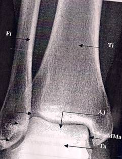
Figure 1: Anteroposterior view of the ankle joint. (Michael et al. 2008)
(Fi= Fibula, Ti=tibia; Ta= talus; Aj= ankle joint; LMa= Lateral Malleolus; MMa= Medial malleolus; MaF= malleolar fossa; DtIfI= distal tibiofibular joint)
Total ankle replacements were introduced in the 1970’s and used to treat a variety of arthritis to include osteoarthritis, rheumatoid arthritis and post-traumatic arthritis.
Michael et al. (2008) describes that to date, most models do not mimic completely the anatomical functionality of a natural ankle joint. However, a number of various total ankle prostheses are available which try to mimic the ankle joint to include the Scandinavian Total Ankle Replacement (STAR) and the Agility Total Ankle System (ATAS). Stress is a measure of the force exerted per unit area of a surface with a deformable body on which internal forces act (Wikipedia 2009). Stress is not uniformly distributed over a cross section of a material body. Hence, the stress at a particular point on a given area is different than the average stress over the entire area (Wikipedia 2009). This essay looks at the stress distribution in the ankle joint and whether any of the current ankle replacement designs have been met.
Stress in the Normal Ankle Joint
The ankle joint is exposed to higher forces than any other joint in the body (Michael et al. 2008). Stauffer et al. (1977) describes that during the stance phase, the ankle joint can experience forces of up to five to seven times the body weight (BW). This compares to approximately three to four times the BW in the knee, and two to three times the BW in the hip. When analysing the stress, the surface area where the force acts is important especially as stress is defined as the force per unit area of a surface. The ankle joint has a surface area that is very similar to that of the hip and knee joint, but the area of contact within the ankle is only one-third of that in the knee or hip joint (Kimizuka et al. 1980).
During walking, substantial forces are created in the ankle joint whilst allowing movement. The normal ankle joint in the sagittal plane can have a range of motion of 70 degrees, which comprises of 50 degrees of plantarflexion and 20 degrees of dorsiflexion (Tooms 1987). This range of motion can be approximately 25 degrees during the stance phase of gait, which comprises of 15 degrees of plantarflexion and 10 degrees of dorsiflexion (Stauffer et al. 1977). The ankle joint can also rotate in the transverse plane about the vertical axis approximately 5 degrees. We find that with movement of the ankle, the centre of rotation of the ankle joint changes (Michael et al. 2008). This occurs because joint gliding takes place as the joint moves from full plantarflexion to dorsiflexion (Nordin and Frankel, 2001). Michael et al. (2008) describes that the load bearing surface contact area of the ankle joint can range from 11 to 13 cm2. The ankle position and action of the ligaments determine the distribution of the load on the talus. On weight bearing, approximately 77-90% of the load is subjected to the talus dome and the remainder over the medial and lateral talar facets (Michael et al. 2008). However, the majority of the load during inversion rests upon the medial talar facet, and during eversion, over the lateral talar facet.
The forces that act on the ankle joint are shown in Figure 2. The bones that make the articular surface of the ankle joint are subjected to stress along their vertical axis by the resultant force Rt. The resultant force Rt can be divided into equal partial forces ri.. Each partial force ri has 2 components: a normal force rn and a tangential force rt. The articular surfaces are subjected to only normal forces, rn. At the medial malleolus, the normal forces rn are smaller than at the trochlear surface. At the fibular malleolar articular surface with vertically orientated articular space, no articular pressure arises from the partial force ri, because rn is zero (Tillmann et al. 1985).
The loading by tensile forces is of greater magnitude in the lateral area of the joint (fibular malleolus). Tillmann et al. (1985) describes that the bony elements of the ankle joint have adapted to the distribution of stress in the ankle joint through the distribution of osseous material in the subchondral bone and by the cancellous architecture. It describes that results from photoelastic model tests reflect such findings when they are subjected to stress by both compressive and tensile forces. Tillman et al. (1985) describes that, ‘’Zones with high fringe orders of isochromatics in the model correspond to area with high density of the osseous tissue in equidensity pictures, and the trajectorial pattern in Plexiglas models mirrors the alignment of compressive and tensile cancellous trabeculae’’.
Figure 2: Forces acting on the ankle joint in the coronal plane. (Tillmann et al. 1985)
The stress at the articulating surface of the tibio-talar joint changes during different motions of the ankle joint. Tochigi et al. (2006) has studied this contact stress through use of real-time contact-stress sensors placed within six normal cadaveric ankle models, to create a geometric model of the tibio-talar articulating surface. The model assumed that as axial load was applied, the contact stress would change with a change in external load through reproducible and specific patterns to maintain stability. The models were all subjected to normal body weight loads. Three situations to include anterior/posterior shear forces, inversion/eversion torques and the internal/external rotation torque were applied independently while the other 2 were maintained constant. Such forces known as secondary forces obtained from the experiment are summarised in Table1.
Ankle Position |
Relative contribution of articular surface restraint during anterior/ posterior movement (%) |
Relative contribution of articular surface restraint during inversion/ eversion (%) |
Relative contribution of articular surface restraint during internal/ external rotation (%) |
15° of dorsiflexion |
64 ± 14 |
58 ± 11 |
22 ± 13 |
0° of flexion |
73 ± 11 |
60 ± 29 |
30 ± 14 |
15° of plantarflexion |
70 ± 13 |
45 ± 31 |
29 ± 8 |
30° of plantarflexion |
75 ± 17 |
33 ± 25 |
27 ± 14 |
Table 1. Ankle joint forces during various angles of flexion- extension (Renstrom et al. 1988)
The experiment showed that anterior/posterior shear forces lead to reproducible positive changes (elevated values) in the anterior/posterior regions respectively. The version torques also lead to reproducible positive changes in the medial / lateral regions, but internal/ external rotation torques lead to reproducible positive changes in only 2 diagonal locations (anterolateral and posteromedial, or anteromedial and posterolateral). Tochigi et al. (2006) using the forces and torques as input, was able to create a model of this articular surface using MATLAB computer programme (version 7), as shown in Figure 2. Nordin et al. (2001) decribes that during movement from plantarflexion to dorsiflexion, the centre of contact area moves from posterior to anterior. Similarly, ankle movement from inversion to eversion, the centre of action moves from medial to lateral. The total contact of the talus was highest, and the average high pressure was lowest in dorsiflexion of the ankle (Calhoun et al. 1994)
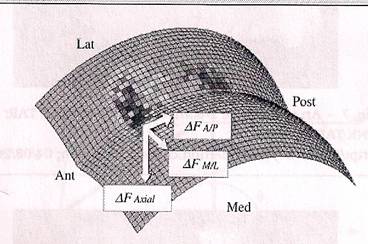
Figure 2: Right ankle geometric model with typical stress-change data (Tochigi et al. 2006)
Saltzman et al. (2005) describes that the upper surface of the talus bone in the frontal plane comprises of 2 domes adjacent to each other. The talus surface was modelled as 2 spheres (radii of 25mm) and the distance between the centres of the spheres to be 20mm. The value of 25mm as the sphere radius is taken as the radius of the talar dome is noted to be 21.3 ± 1.8mm (Michael et al. 2008). The articulating tibio-talar surface was analysed and changes were observed regarding varying external load to maintain stability. The contribution of the articulating surface to the joint stability being 70% of the anterior/posterior stability, 50% of inversion/eversion stability, and 30% of internal/external rotation stability (Michael et al. 2008).
Total ankle Replacements
Each artificial ankle prosthesis has 2 parts named the tibial component and the talus component. The tibial component replaces the socket portion of the ankle, where as the talus component replaces the top of the talus. The tibial component can comprise of 2 parts, which includes a flat metal tray that is attached directly to the tibia and a plastic cup that attaches to this metal tray acting as a socket for this artificial joint replacement. These components are illustrated in Figure 3.
Figure 3: An artificial ankle replacement illustration (Orthopod. 2009)
The ideal design for a total ankle replacement aims to utilise the available bone stock, have low stress on the bone-implant interface and minimise bearing wear (Story et al. 2008). It is also important that the surgical exposure is adequate, consistent and reproducible, and it allows the possibility for revision arthroplasty or salvage surgery.
The ankle joint can carry loads of up to five to seven times the body weight and the surface area possible for the ankle replacement implant is significantly less than the knee or hip (stauffer et al. 1977). The first generation ankle implants lacked success for two important reasons: a limited articular construct with limited motion in comparison to the normal joint allowing increased stress at the fixation surface, and failure to preserve the strongest bone. This led to frequent bone collapse from the increase stress at the articulating surface.
The two 2nd generation ankle replacements that are commonly used and will be analysed here include the ‘’Scandinavian Total Ankle Replacement’’ (STAR) and the ‘’Agility Total Ankle system’’ (ATAS). The rotational and sliding movements of the ankle were achieved by these 2 and 3 component designs.
The STAR Prosthesis
The STAR prosthesis consists of three components that can be placed cemented or uncemented. There is a talus cup, which covers the lateral and medial facets and a polyethylene meniscus. The tibial part is a flat rectangular piece and has 2 parallel cylinders on its back that fit into the tibia. The surface towards the bone is titanium beaded with electrochemically added calcium phosphate for rapid ingrowth. The 3rd component is the polyethylene meniscus, which is floating between the 2 pieces of the metal (DeOrio et al. 2006). Figure 4 shows the STAR prosthesis.
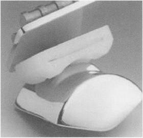
Figure 4: The STAR prosthesis
Valderrabano et al. (2004) has described the long-term outcome of this prosthesis received by 68 patients at follow-up of 3.7 years. Mechanical failure accounted for 13% of the patients. 54% had decreased pain and were satisfied with the outcome. 21% of the patients required further operations and 66% of patients showed hypertrophic bone formation.
The results have showed that mechanical failure is significant at 13%. With ankle joint replacement we need to take into account stress shielding of bones by the implant. It is thought that when the metal prosthesis is attached to the talus or tibia, it
will carry a fraction of the load, which would otherwise be carried by the intact skeleton if there were no abnormality requiring the implant (Lucas et al. 1998). This stress sharing leads to a reduction in the stress and strain in the adjacent bone. This reduction in the stress can lead to atrophic remodelling (according to Wolfe’s Law) which can subsequently cause loss of attachment of the prosthesis or fracture of the bone next to the prosthetic area (Lucas et al. 1998). This type of reaction is described as stress-shielding osteoporosis or stress shielding osteopaenia.
The polyethylene component has an important role in biomechanics of the ankle joint as it relieves the stress on the bone-prosthesis surface caused by movement of the ankle (DeOrio et al. 2006). It does this by floating between the metal surfaces so the forces acting in the ankle joint are spread over a wider area. This component has led to complications such as wearing of the polyethylene and is one of the reasons in addition to loosening to explain the need for revision of the prosthesis
Although this prosthesis tries to meet the ideal requirements of the ankle joint, the ideal requirements have not been fully met based on the stress distribution, as the risk of component failure (loosening) is high and approximately only 54% were pain free and satisfied.
The ATAS Prosthesis
The ATAS has 2 components separated by a polyethylene liner, which are attached uncemented to the bone interfaces. The prosthesis replaces the medial, lateral and superior articulating surfaces of the ankle joint. The articular surface of the tibial component is larger than the talar component (Michael et al. 2008). The prosthesis surface has been textured with a titanium spray to allow the bone to grow into the prosthesis. It uses an arthrodesis between the fibula and the tibia to increase the ingrowth area (Revell et al. 2008) and this gives the ankle constant bony contact.
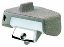
Figure 5: The ATAS prosthesis (Mercy et al. 2009)
Knecht et al. (2004) has described the long-term outcome of this prosthesis received by 132 patients at follow-up between 7-16 years. Mechanical failure accounted for 38% of the patients. 90% had decreased pain and were satisfied with the outcome. The revision rate was only 11%
The prosthesis failure was noted to be significantly higher for the ATAS prosthesis in comparison to the STAR prosthesis. Possible reasons include: stress shielding of bones by the implant as described above, but also the construct allows more movement than the STAR prosthesis. Michael et al. 2008 describes that the talar and tibial component have incongruent articulations that allow sliding as well as the rotational motions that are similar to the normal ankle joint. This would create more forces acting on the talus and tibial component especially with varying movement increasing the susceptibility to loosening.
The ATAS prosthesis has a narrow talar component articulating with a wider tibial component. The smaller talar component ensures the 2 components do not sit tightly and this was the design concept to help decrease shear stress and to allow normal rotation with ankle movement (Johnson et al. 2009). This is likely to have a significant effect on polyethylene wear and further explains the risk of failure and need for revision surgery. The subsidence of the implant into the tibia was noted to be common and so the ATAS prosthesis was modified to include fusion of the tibia and fibula distally acting as a barrier to tibial subsidence. This change does help in reducing risk of complication but it does prevent normal biomechanical rotation of the tibia and fibula.
Although again this prosthesis tries to meet the ideal requirements of the ankle joint, the ideal requirements have not been fully met based on the stress distribution, as the risk of component failure (loosening) is significantly high. Although, we do find that 90% of patients were pain free and satisfied which suggests that it is successful in doing its function but at the high expense of risk of mechanical failure.
Conclusion
Total ankle replacements have an important role to mimic the anatomical and functional role of the normal ankle joint. Numerous prostheses have been developed to include the STAR and ATAS prosthesis. The ankle joint can sustain forces of up to five to seven times the body weight during the stance phase, and although the articulating surface area is similar to that of the hip or knee, area of contact within the ankle is only one-third of that in the knee or hip joint (Kimizuka et al. 1980). The ankle position and action of the ligaments are said to determine the distribution of the load on the talus. On weight bearing, approximately 77-90% of the load is subjected to the talus dome and the remainder over the medial and lateral talar facets (Michael et al. 2008).
Outcome analysis for the STAR prosthesis and ATAS prosthesis have revealed that component failure is a significant complication with 13% of the STAR, and 38% of the ATAS failing. This may be due to stress shielding between the implant and the bone leads to a reduction in the stress and strain in the adjacent bone. This reduction in the stress can lead to atrophic remodelling (according to Wolfe’s Law) which can subsequently cause loss of attachment of the prosthesis or fracture of the bone next to the prosthetic area (Lucas et al. 1998). The ATAS prosthesis has proven to have much better patient satisfaction and lower revision rate in comparison to the STAR implant, but is associated with an increased mechanical failure rate. Although current designs exemplified by the ATAS may give excellent patient satisfaction in terms of pain, based on a stress distribution they have not fully met the ideal requirements of a total ankle replacement as reflected by the significant mechanical failure rate.
Reference :
- Anderson, T., Montgomery F., Carlsson, A. 2004. Uncemented Star Total Ankle Prosthesis. Journal of Bone and Joint Surgery 86-A Suppl 1(Pt 2), pp. 103-11.
- Calhoun, J.H., Eng, M., Li, F., et al. 1994. A comprehensive study of pressure distribution in the ankle joint with inversion and eversion. Foot Ankle Int 15(3), pp. 125-33.
- DeOrio, J.K. 2006. You Mean You Can Replace the Ankle Joint. Northeast Florida Medicine 57(3), pp. 9-12.
- Johnson, A.R. 2009. A closer look at the future of ankle arthroplasty. [Online]
Available at: http://www.podiatrytoday.com/a-closer-look-at-the-future-of-total-ankle-arthroplasty
[Accessed: 23 December 2009].
- Kimizula, M., Kurosawa, H., Fukubayashi. 1980. Load bearing pattern of the ankle joint: Contact area and pressure distribution. Archives of Orthopaedic and Trauma Surgery 96(1), pp. 45-9.
- Knecht, S.I., Estin, M., Callaghan, J.J., Zimmerman, M.B., Alliman, K.J., Alvine, F.G., Saltzman, C.L. 2004. The agility total ankle arthroplasty. Seven to sixteen-year follow-up. Journal of Bone and Joint Surgery 86-A(6), pp. 1161-71.
- Koval, K.J., Zuckerman, J.D. 2006. Handbook of Fractures. Philadelphia: Lippincott Williams and Wilkins.
- Lucas, G.L., Cooke, F.W., Friis, E.A. 1998. A primer of Biomechanics. Germany: Springer Verlag.
- Nordin, M., Frankel, V.H. 2001. Basic Biomechanics of the Musculoskeletal System. Philadelphia: Lippincott Williams and Wilkins.
- Mercy. 2009. Total Ankle Replacement. [Online]
Available at: http://www.drmyerson.com/conditions/ankle_arthritis/total_replacement.html
[Accessed: 12 December 2009].
- Michael, J.M., Golshani, A., Gargac, S., Goswami, T. 2008. Biomechanics of the ankle joint and clinical outcomes of total ankle replacement. J Mech Behav of Biomed Mater 1(4), pp. 276-94.
- Munaghan, J.M., Warnock, D.S., Henderson, S.A. 2005. Total Ankle Replacement. Early experience with STAR prosthesis. Ulster medical Journal 74(1), pp. 9-13.
- Orthopod. 2009. A patient’s Guide to Artificial Joint Replacement of the Ankle. [Online]
Available at: http://eorthopod.com/public_education/6463/…
[Accessed: 12 December 2009].
- Revell, P.A. 2008. Joint Replacement Technology. Cambridge: Woodhead Publishing.
- Stauffer, R.N., Chao, E.Y.S., Brewster, R.C. 1977. Force and motion analysis of the normal, diseased, and prosthetic ankle joint. Clinical Orthopaedics 127, pp. 189-196.
- Story R. 2008. Total Ankle Replacement. [Online].
Available at: http://www.medicalhub.com.au/componrnt/option,com_docman/…/gid,63
[Accessed: 12 December 2009]
- Tooms, R.E. 1987. Arthroplasty of ankle and knee. In: Crenshaw, A.H. eds. Campbell’s Operative Orthopaedics. 2nd ed. St. Lois: Mosby Company, pp. 1145-1150.
- Valderrabano, V., Hintermann, B., Dick, EW. 2004. Scandinavian total ankle replacement: A 3.7 year average followup of 65 patients. Clinical Orthopaedic Related Research 424, pp. 47-56.
- Wikipedia. 2009. Stress (Mechanics). [Online].Available at: http://en.wikipedia.org/wiki/Stress_(physics) [Accessed:12 December 2009]
|