|
Abstract:
Background & purpose:
The Locking Compression Plate (LCP) system offers a number of advantages in fracture fixation combining angular stability through the use of locking screws with traditional fixation techniques. However, the system is complex, requiring careful attention to biomechanical principles and good surgical technique.
Methods:
From a series of clinical cases, where locking plate fixation was used in fractures of long bones, three were selected. Patient specific geometric information was obtained from AP and lateral plain radiographs, and the Finite Element (FE) models were generated manually.
Results:
The first case study highlighted the importance of the working length on the construct stability. By increasing the working length the construct became more flexible. The resulting increase in interfragmentary motion promoted indirect healing with the formation of callus.
In the second case study, plate breakage occurred as a result of an inappropriate fixation technique. The fixation involved the use of locked screws at the level of the fracture passing the fracture line. This reduced the flexibility of the implant which hindered the micro-motion needed for callus formation. Fatigue failure eventually occurred due to cyclic loading past the yield stress of the LCP.
In the third case study the long working length of the construct made it relatively flexible. The larger area of stress distribution on the plate reduced the local strain, resulting in a protective effect against fatigue failure of the implant.
Interpretation:
In Conclusion, successful application of the LCP demands a good understanding of the biomechanics and careful pre-operative planning.
J.Orthopaedics 2011;8(1)e3
Keywords:
Finite; Element; Analysis; Locking; Plate; Non-union; Breakage.
J.Orthopaedics 2011
Introduction:
Since the first plate osteosynthesis reported in 1886 by Hansmann [1] from Hamburg, plating methods and surgical techniques have changed to ensure the best possible fracture healing.
There have been multiple attempts to improve fixation of conventional plates to compromised bone. These have included the use of cement to improve screw torque. Schuhli nuts [2] and Zespol plates [3] were used in early attempts to convert a conventional plate into a fixed-angle device whereby the plate functions like an “internal fixator.” The AO (Arbeitsgemeinschaft fur Osteosynthesefragen) group refined these early attempts and introduced the Point Contact Fixator (PC-Fix) [4] and the Less Invasive Stabilization system (LISS plate) [5-6]. The clinical successes of these plates led to the introduction of the Locked Compression Plate and the recent proliferation of locked-plate designs by several manufacturers.
Traditionally, plate osteosynthesis employed the principles of rigid fixation (leading to primary bone union without the formation of callus) with stability of the construct enhanced by compressing the plate directly onto bone. This method involves the stripping of periosteum and compression of the plate against the bone, both of which can lead to ischaemia and necrosis of bone directly beneath the plate. Locking plates, such as the LCP, provide ‘angular stability’ at the plate-screw interface, which allows extra-periosteal fixation of the plate to the bone. By preserving periosteal blood supply to the bone it addresses the importance of the biological factors involved in fracture healing. The principles of flexible fixation are employed where the goal is for indirect healing with the formation of callus.
Bearing this in mind, one must be aware of a balance between flexible fixation, which encourages callus formation and promotes the healing process, and an unstable fixation, which leads to non-union and implant failure.
Although the LCP system offers a number of advantages in fracture management, its successful use requires careful pre-operative planning, consideration of biomechanical principles, and the use of the appropriate plate and screws combined with good surgical technique. Failure to address these issues can lead to potential pitfalls in terms of implant breakage or non-union.
Little recommendations exist in the current literature for the control of construct stability or how the risk of implant failure can be reduced for the LCP.
Aim:
To highlight the biomechanical principles and the potential pitfalls of the LCP system using Finite Element Analysis of three patient-specific clinical cases.
Materials and methods:
The three analysis cases were drawn from an ongoing clinical series where locking plate fixation was used in fractures of long bones.
Finite Element Analysis:
Linear FEA was performed using ANSYS Version 10. The FE models were generated manually using patient specific geometric information that was obtained from AP and lateral plain radiographs.
The implant material was pure titanium represented in the FE model by its Young’s modulus of 115 GPa and a Poisson’s ratio of 0.34. The tibia was characterized by distinguishing between cortical bone and trabecular bone. The cortical bone was modelled with a Young’s modulus of 17 GPa and a Poisson’s ratio of 0.3, whereas the cancellous bone was modelled with a Young’s modulus of 700 MPa, and a Poisson’s ratio of 0.2.
A load equivalent to the weight of the patient was applied to each FE model. This axial load was simulated by fixing the distal end of the model and applying a force through the bone at the proximal end.
The FE models were used to analyse and quantify the magnitude of displacement at the fracture site and the stresses experienced by the implant. The locations of maximum stresses experienced by the implant were also determined. The results were logged and analysed using Microsoft Excel spreadsheets.
Case 1

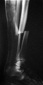
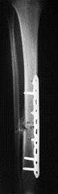
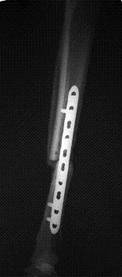
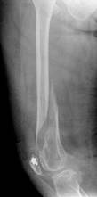
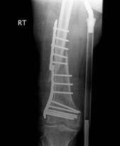
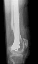
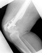
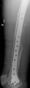
A 23-year-old man with no background history sustained a transverse fracture (Fig. 1.a) of the right tibia and fibula (AO 42 A3) after receiving a kick on the shin while playing Gaelic football. The fracture was stabilised with a 4.5mm Narrow LCP (Fig. 1.b&c) with 10-Combi holes using 6 looked screws (two screws at either end of the plate and two screws adjacent to the two middle holes over the fracture site).
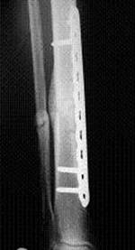
Six months later on follow-up radiography there was no visible callus formation at the fracture site. At this stage he underwent removal of the two inner-most screws. Radiography six months after the 2nd procedure revealed that the fracture had healed with marked callus formation (Fig. 1.d).
a. b. c. d.
Fig 1. Clinical case of a tibial fracture stabilised with a 4.5mm LCP in a 23 years old patient. The preoperative (a), post operative (b&c) and follow-up radiographs six months post removal of the two inner-most screws (d) are shown.
Finite Element Analysis
Two finite element models were created by using patient specific geometric information obtained from plain radiographs (fig. 2). Model (A) represents the fracture fixed with a 4.5mm narrow LCP using 6 locked screws. In model (B) the two innermost screws have been removed. The number and position of screws used in each scenario is shown in (fig. 3). A Load of 833N (patient weight 85kg) was then applied through the bone at the proximal end in each case.
It appears to be essential that a sufficient length of plate is left without screws at the level of the fracture to achieve adequate flexibility of the construct and to promote callus formation through micro-motion. After removal of the two screws, gap closure occurred under load conditions (Fig. 5).
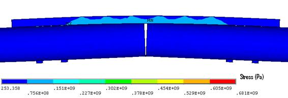
Figure 5. Implant stress contour (Model B). Note: the maximum plate stress was 235MPa.
Also, the maximum von Mises stress in the plate and the two innermost screws decreased significantly when the bridging length was increased (model B) because bone contact occurred under load conditions. Removing the two innermost screws, reduced the stress in the plate by 58% and in the screw by 66% (Fig. 6).
The stress concentrations were localised to a point or a specific region of the implant. The majority of stresses were therefore below the yield stress, and hence the implant would not have deformed permanently (Fig. 7). Despite this, these stress concentrations can indicate where fatigue failure might occur.
Figure 6. Max stress plate and screw stress before (Model A) and after (Model B) removing the two innermost screws.
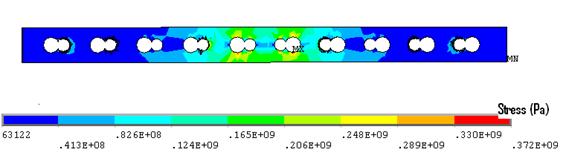
Figure 7. Plate stress (Model A), note the majority of stresses were below the yield stress (235MPa).
Case 2

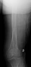
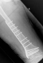
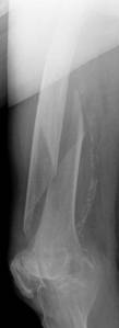
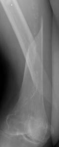
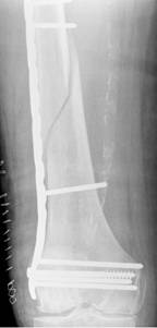
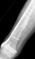
A 74-year-old woman with osteoporosis, polymyalgia Rheumatica and COAD suffered a spiral fracture of the distal femoral diaphysis (AO 32 B1). The fracture (Fig. 8.a&b) was treated by open reduction and stabilisation with a 15-hole LCP Distal Femur Plate (Fig. 8.c&d) using 13 looked screws (one hole in the shaft portion of the plate at the fracture site and one hole in the head of the plate were left unoccupied).
a. b. c. d.
e. f. g.
Figure 8. Clinical case of a femoral fracture in a 74 year old patient treated with a LCP. The preoperative (a&b), post operative (c&d), implant failure at 22weeks (e&f) and follow up radiographs one year after IM nailing (g) are shown.
Follow-up radiographs after 22 weeks (Fig. 8.e&f) revealed plate breakage at the middle part of the original fracture. No callus formation was visible at the level of the fracture. She then underwent IM nailing of her right femur and subsequent radiography after 1 year revealed complete consolidation with marked callus formation (Fig. 8.g).
Finite Element Analysis
A finite element model (Fig. 9) was created by using patient specific geometric information obtained from plain radiographs. A load of 539N (patient weight 55kg) was then applied through the femoral head.
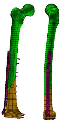
Figure 9. Finite element model of the locking plate system (Case study 2).Results
Due do the very short working length (one unoccupied screw hole over the fracture site) and insertion of locking screws at the level of the fracture passing through the fracture line, the construct was rigid with an axial stiffness of (2.0 kN/mm). This hindered the micro-motion needed for callus formation.
The maximum Von Mises stress in the plate (299MPa) was found at the outer edges in the unoccupied screw-hole over the fracture site (Fig. 10). This is significantly higher than the yield strength of stainless steel (235MPa). Failure of the fracture to heal at 22 weeks meant that the stresses experienced by the implant remained under the load-bearing rather than the load-sharing scenario. Fatigue failure occurred at this site due to cyclic loading past the yield stress
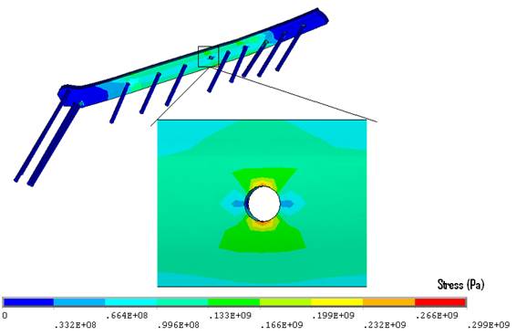
Figure 10. Stresses experienced by the LCP plate. Note: the maximum plate stresses were concentrated at the edges of the unoccupied screw-hole where fatigue failure occurred
Case 3

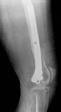
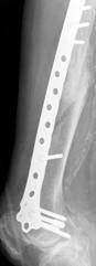
A 91-year-old nun with background history of melanosis coli and osteoarthritis tripped and fell indoors sustaining a spiral fracture (Fig. 11a&b) of the right distal femoral diaphysis (AO 32 B1). The fracture was stabilised with a LCP Distal Femur Plate (Fig. 11c&d) using 7 locked screws and one partially threaded cancellous screw (6 screw holes were left unoccupied over the fracture site). Follow-up radiographs (Fig. 11e&f) 6 months later revealed indirect bone healing with marked callus formation.
a. b. c. d.
e. f.
Figure 11. Clinical case of a femoral fracture in a 91 years old patient treated with a LCP. The pre-operative (a&b), post operative (c&d), and follow-up radiographs at 6 months post-op (e&f) are shown.
Finite Element Analysis
A finite element model (fig. 12) was created by using patient specific geometric information obtained from plain radiographs. A load of 569N (patient weight 58kg) was then applied through the femoral head.
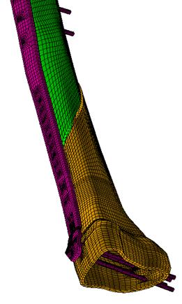 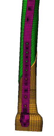
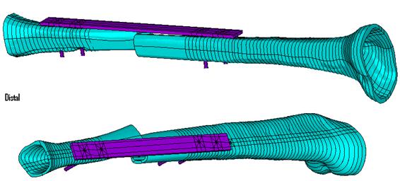
Figure 12. Finite element model of the locking plate system (case study 3).
Results
Due to the large working length (6 unoccupied screw holes over the fracture site) the construct was relatively flexible with an axial stiffness of (0.9 kN/mm). This seems to have promoted callus formation through micro-motion.
The maximum von Mises stress (149 MPa) was found in the innermost screw distal to the fracture site. The maximum plate stresses (117 MPa) were concentrated at the outer edges in the unoccupied screws-holes over the fracture site. It should be noted that all stress concentrations in this case (fig. 13) were below yield strength of stainless steel (235 MPa).
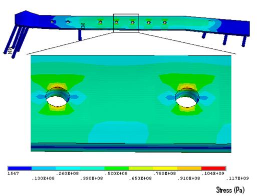
Figure 13. Stresses experienced by the LCP plate. Note: all stress concentrations in this case were below yield strength of stainless steel.
Discussion
In the past, the appearance of callus in plate osteosynthesis was assumed to indicate a lack of stable fixation. Today, indirect healing with callus formation is no longer regarded as a disturbance to healing but a welcome sign of a positive bone reaction. However, in the stabilisation of fractures of long bones there is a fine line between flexible fixation, which enhances callus formation and improves the healing process, and an unstable fixation, which leads to non-union and/or implant failure.
When selecting an internal fixator for plate osteosynthesis, the main problem is to determine how the mechanical environment of the fracture and implant failure can be controlled. The first clinical results with internal fixators were promising [7-8], although determining the number and position of screws was mainly based on clinical experience with conventional plates as described in numerous studies [9-10].
The first case study highlighted the importance of the working length on the construct stability. By increasing the working length from four to six empty screw-holes over the fracture site, the construct became 18% more flexible in compression. These results are in agreement with those of biomechanical investigations for conventional plating techniques [11]. The resulting increase in interfragmentary motion promoted indirect healing with the formation of callus.
In this case, as the system become more flexible (longer bridging length) and bone contact occurred, the stress in the plate was reduced by 58% (fig. 6 ) hence less force was needed to achieve interfragmentary contact and this was reflected in lower peak stress magnitudes.
Hardware failure (plate failure, or screw breakage) is a complication that has been reported to occur in as many as 7% of plate fixations [12]. In the second case study, plate breakage occurred as a result of an inappropriate fixation technique, rather than the choice of plate. The fixation involved the use of locked screws at the level of the fracture passing the fracture line. The distribution of the screws, which have been shown to be important factor determining the stability of the fixation, was similar to those used in a conventional compression plate [13]. However, the insertion of locking screws at the level of the fracture reduces the flexibility of the implant [13] which hinders the micro-motion needed for callus formation. Fatigue failure eventually occurred due to cyclic loading past the yield stress of the LCP. Failure occurred in the region of maximum von Mises stress in the plate at the outer edges of the unoccupied screw-hole over the fracture site.
In 2005, Gardner et al. [14] reported in vitro biomechanical results of the LCP when compared with the LC-DCP. While the LC-DCP continually failed at the most distal screw the LCP followed no specific pattern of failure. On the contrary Stoffel et al. reported in 2003 that in bridge plating with the LCP plate failure mostly occurred at the DCP hole near the fracture gap, which is in agreement with the finding of this study. One possible reason for such discrepancies is the specimen used. Gardner et al. (Gardner et al., 2005) performed their test using cadaveric radii while stoffel et al. [13] used composite cylinders.
In the third case study the long working length of the construct made it relatively flexible. This allowed healing through lateral callus formation from the micro-motion induced by the weight-bearing.
The Von Mises stresses in the LCP plate and screws are considerably lower in the third case-study compared to the previous two. This is due not only to the large working length but also the relatively longer plate [13]. As relatively few screws were inserted the plate leverage increased which decreases the individual load on each screw. Leaving six empty screw-holes over the fracture meant that larger area of stress distribution on the plate was achieved. Bending a plate over a longer segment reduces the local strain, resulting in a protective effect against fatigue failure of the implant.
The experience to date with the LCP system has shown that it provides effective fixation in a wide range of fracture, with a low incidence of implant related complications [15].
However, as illustrated by cases reported here, successful application of the LCP system needs careful preoperative planning and attention to the biomechanical principles that have been incorporated in its design.
References:
1. Hansmann, C . Eine neue Methode der fixierung der Fragmente bei complicierten Frakturen. Verh Dtsch Ges Chir. 1886, 158.
2. Simon JA, Dennis MG, Kummer FJ, Koval KJ. Schuhli augmentation of plate and screw fixation for humeral shaft fractures: a laboratory study. J Orthop Trauma. 1999 Mar-Apr; 13(3):196-9
3. Ramotowski W, Granowski R. Zespol. An Original method of stable osteosynthesis. Clin Orthop Relat Res. 1991 Nov; (272):67-75.
4. Borgeaud M, Cordey J, Leyvraz PE, Perren SM. Mechanical analysis of the bone to plate interface of the LC-DCP and of the PC-FIX on human femora. Injury.2000; 31 Suppl 3:C29-36.
5. Cole PA, Zlowodzki M, Kregor PJ. Less Invasive Stabilization System (LISS) for fractures of the proximal tibia: indications, surgical technique and preliminary results of the UMC Clinical Trial. Injury. 2003; 34 Suppl 1:A16-29.
6. Frigg R, Appenzeller A, Christensen R, Frenk A, Gilbert S, Schavan R. The development of the distal femur Less Invasive Stabilization System (LISS). Injury. 2001 Dec; 32 Suppl 3:SC24-31.
7. Babst R, Hehli M, Regazzoni P. [LISS tractor. Combination of the "less invasive stabilization system" (LISS) with the AO distractor for distal femur and proximal tibial fractures]. Unfallchirurg. 2001 Jun;104(6):530-5.
8. Karnezis IA, Miles AW, Cunningham JL, et al. "Biological" internal fixation of long bone fractures: a biomechanical study of a "noncontact" plate system. Injury. 1998 Nov; 29(9):689-95
9. El-Maraghy AW, ElMaraghy MW, Nousiainen M, et al. Influence of the number of cortices on the stiffness of plate fixation of diaphyseal fractures. J Orthop Trauma. 2001 Mar-Apr; 15(3):186-91
10. Aro HT, Kelly PJ, Lewallen DG, Chao EY. The effects of physiologic dynamic compression on bone healing under external fixation. Clin Orthop Relat Res. 1990 Jul;(256):260-73
11. Compte P, Straumann F. Influence of unoccupied holes on the fatigue behavior of bone fixation plates. In: Perren SM, Schneider E, eds. Proceedings of the European Society of Biomechanics: Current Interdisciplinary Research. Amsterdam: Martinus Nijhoff. 1985; 459-46412. Riemer BL, Butterfield SL, Burke CJ, 3rd, et al. Immediate plate fixation of highly comminuted femoral diaphyseal fractures in blunt polytrauma patients. Orthopedics. 1992 Aug; 15(8):907-16
13. Stoffel K, Dieter U, Stachowiak G, Gächter A, Kuster MS. Biomechanical testing of the LCP – how can stability in locked internal fixators be controlled? Injury. 2003 Nov; 34 Suppl 2:B11-9
14. Gardner MJ, Brophy RH, Campbell D, Mahajan A, Wright TM, Helfet DL, Lorich DG. The mechanical behaviour of locking compression plates compared with dynamic compression plates in a cadaver radius model. J Orthop Trauma. 2005; 19(9), 597-603.
15. Sommer C, Gautier E,Müller M, et al. First clinical results of the Locking Compression Plate (LCP). Injury.2003; 34(suppl 2):43–54.
|